User Guide
Gage R&R
Gage R&R helps qualify a measurement system, i.e. verification that a measurement system's variability is compatible with the variability of the quantity to be measured.

It is considered necessary to have a ratio of 4 between parts variability and measurement variability. This ratio is called Cpc production:
Cpc production therefore depends on the dispersion of parts because, while we want to characterize a measurement instrument, we want this characterization to be independent of the production variability. We will therefore introduce a new kind of variable that helps characterize the measurement instrument, not based on parts dispersion but based on the parts' tolerance interval.
The measurement instrument will be characterised in the same way that we calculate capability:
• Either by the Cpc (Control Process Capability):
- Or by the RR (Repeatability and Reproducibility):
As you may have noticed, the two indicators represent the same thing and have the following relationship:
Therefore these rules are normally applied:
| Cpc | GRR% | |
|---|---|---|
| Unacceptable | <3 | >30% |
| Process limit | >3 et < 4 | <30% et >20% |
| Acceptable | >4 | <20% |
| Excellent | >8 | <10% |
Ellistat use :
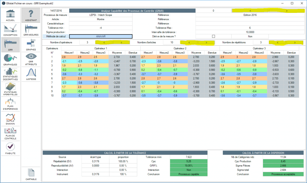
For an R&R to be carried out, the number of parts, number of operators and number of repetitions is defined in order to set the table's dimensions. Calculations are carried out once the table is complete. The number of parts, operators and repetitions may be changed after inputting their values.
When placing the mouse over a figure a brief reminder of the figure's meaning appears

Several R&R's can be carried out during the same Ellistat session. You can pass from one R&R to another by clicking on the arrows
Interpreting the graphs:

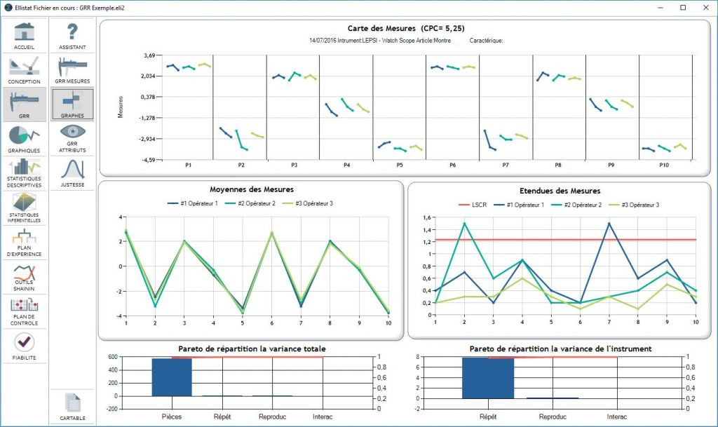
The graphs create a visual representation of the result of the calculations.
The first graph gives the repetition of the measurements carried out for each part measured and for each operator.
The second line of the graph gives the average measurement by part and by operator as well as the range chart. A point that is outside of the control on the range chart probably indicates an abnormal measurement.
Finally, the bar graphs show the variance distribution.